Hydraulic Modeling, the often overlooked factor in treatment plant design
* Note - this material was also presented as an article in the Water Environment Federation's "Influents Magazine" (Focus on Modeling), Spring 2009.
Treatment plant hydraulics is often overlooked as one of the most
important aspects of treatment plant design, especially in plant
upgrade scenarios where retrofitting new equipment or processes
into the existing treatment train will create additional
hydraulic restrictions. Many existing plants already have
a minimal amount of head available for passing peak flows
through the system, which can make plant upgrades even more of a
challenge.
The Bethel Park
Municipal Authority located outside of Pittsburgh, Pennsylvania
faced this exact problem when recently upgrading their trickling
filter wastewater treatment plant. The existing trickling
filter system involved a confusing scheme of recycling flows
between the one trickling filter pump station and both trickling
filters. Rather than the filters operating in series (as
originally designed), they often operated in parallel due to the
poorly designed pump station wet well. A process flow
diagram of the existing treatment plant is shown in Figure I to the right.

In order for the
trickling filters to function as intended in a true series
operation, a separate pump station had to be designed that would
allow flow to be pumped directly to each filter from its own
pumping system. Also included in the design were unique
flow distribution boxes that managed the forward flows to the
filters, return flows from the filters, and provided for the
flexibility of either pump station being able to pump to either
filter should one pump station be off-line. While the
concept behind the flow distribution scenarios was fairly
simple, the hydraulics associated with making the entire design
work was not. Each distribution box has multiple chambers
that direct the flow to its intended location within the
process. Varying floor inverts and weir elevations had to
be established that would ensure that the appropriate amount of
forward flow and return flows were getting to each filter.
Additionally, since the available head throughout the treatment
plant was very limited, the additional head loss created by the
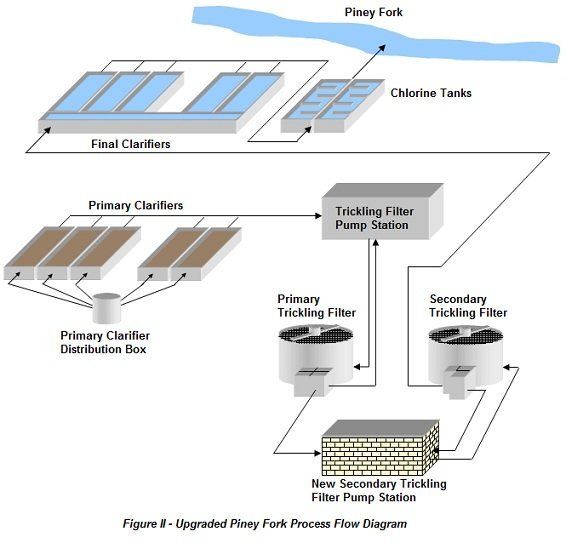
upgraded system had to be minimal. A process flow diagram
of the upgraded treatment plant is shown in Figure II to the right.

With a wide
range of flows possible at the treatment plant (3 MGD - 20 MGD),
hydraulic modeling was determined to be the best solution for
analyzing all of the possible hydraulic scenarios and determine
the design that would be best suited for the hydraulic
limitations. In order to model the hydraulics for the
Bethel Park plant, Visual Hydraulics was determined to have the
most flexibility and would allow designers to easily change
hydraulic features, return flows, and model the hydraulics over
the range of flows typically experienced at the plant. In
this case, the software was used to model the flow distribution
boxes in terms of box size, invert elevations, and weir
elevations. Through modeling it was also determined that
the best way to control the return flow to each of the trickling
filters was to place gates on the distribution box effluent
lines that would open and close based on the amount of flow
being conveyed to the filters. Under lower flows, the
gates would remain mostly closed, allowing more flow to be
recycled. As the flows in the plant would rise (typically
as the result of rainfall events), the gates would open to allow
more flow to be conveyed as forward flow through the trickling
filters to the secondary clarifiers. This permits the
plant to avoid unnecessarily recycling flows that are mostly
rainwater, which can hurt the biological process. A
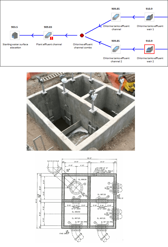
diagram of the hydraulic profile created with Visual Hydraulics
for the Piney Fork treatment plant is shown to the right.
Detailed
hydraulic modeling was required to determine how much head loss
should be generated by the distribution box effluent gates to
produce the desired amount of flow being returned to the
filters. This had to be balanced with the amount of flow
to be passed onto the next process in the system. Since
the return flows are conveyed over a weir before being pumped
back to the appropriate trickling filter, the weir elevations
had to be set based on the gate hydraulics as well. Only
hydraulic modeling and the flexibility that a computer generated
model can provide could make this complex analysis as pain free
as possible.
The Piney Fork
plant upgrade project was completed in later summer of 2007.
The plant has received numerous peak flow events that have met
or exceeded the plant capacity of 20 MGD since the plant upgrade
was constructed. The hydraulics of the new trickling
filter system have performed as predicted, and the trickling
filters are producing significantly lower BOD and NH3
concentrations than they have since they were originally placed
into operation over 50 years ago.


