Visual Hydraulics Design Recommendations

Visual Hydraulics Design Recommendations:
Treatment
plant hydraulic design considerations:
Flow
conditions to consider: minimum, average, peak, ultimate
Pipes
- Avoid
unnecessary fittings, be as simplistic as possible. One standard 90 degree bend can have much less head
loss than two 45 degree bends:

- Use of a fitting database. Pipe K values can be reported differently in a variety of sources, and the designer needs to take this into consideration.
- Minimum flow velocities of 2 feet per second (0.61 m/s) are usually desired to prevent solids from settling in the pipe.
- Avoid siphons (depressed sewers) where possible, and if siphons are to be used, ensure that flow velocities will be high enough to cleanse the pipe. At least 3 feet per second (0.91 m/s) is the recommended minimum velocity.
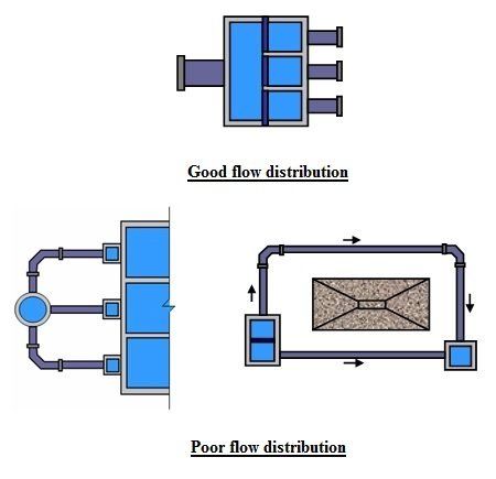
- Run parallel pipes along as similar a path as possible. Pipe systems that have pipes laid out with a high degree of variance may affect the upstream hydraulics and contribute to an unequal distribution of flows.
- Understand that the hydraulic analysis of pipes is not an exact science. K values and roughness coefficients (relative roughness "e" value, Hazen-Williams "C" coefficient, etc) are empirical estimates. Pipe age can greatly increase friction losses, as well as the solids content of the flow. Be conservative, but don't "over design".
- Use
good flow splitting techniques. If more than one pipe is used to convey flow to
multiple units, equally divide the flow using a flow
distribution structure or other technique. This is especially important for multiple pipes that
do not have the same characteristics, i.e. length and/or
fittings. Less
flow will go through pipes with higher head losses. This may cause a significant variation in the amount
of flow to each unit (see below).

Channels
If
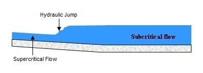
possible, keep channel slopes to a minimum. Steeply sloped channels can create high flow
velocities and create unwanted flow scenarios, such as
hydraulic jumps. The
hydraulics of these flow scenarios can be difficult to
predict:

Channels
should maintain a constant cross section wherever possible.
Changes in channel depth or shape can alter flow patterns
which in turn can create unwanted headlosses. These
headlosses may be difficult to analyze.
Channel
networks should distribute flow as equally as possible.
This can be done by flow splitting techniques. Examine the
channel network used to distribute flow to 9 final clarifiers
shown below. Flow is distributed to each clarifier via
channel "reaches", which branch off from the main
distribution channel. Flow will always follow the path of
least resistance or head loss. In the design below, more
flow will go to clarifiers 1, 2, and 3, and the least amount of
flow will go to clarifiers 7, 8, and 9. This is because
the head loss from the main channel entrance to clarifiers 7, 8,
and 9 will be greater than the head loss to clarifiers 1, 2, and
3. Depending on the design, this loss may be fairly
insignificant and there may be virtually equal distribution.
But on long channel runs or other factors such as differing
geometry, this flow distribution anomaly can create hydraulic
issues, especially under higher flows.

